


What keeps a massive open-cast mine from collapsing? Slope Stability
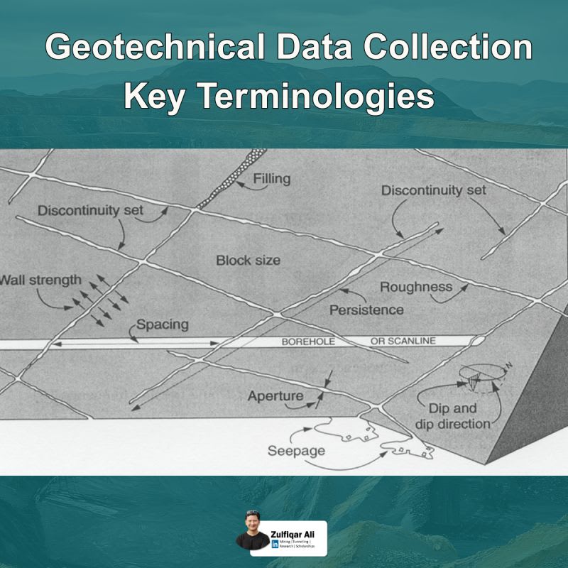
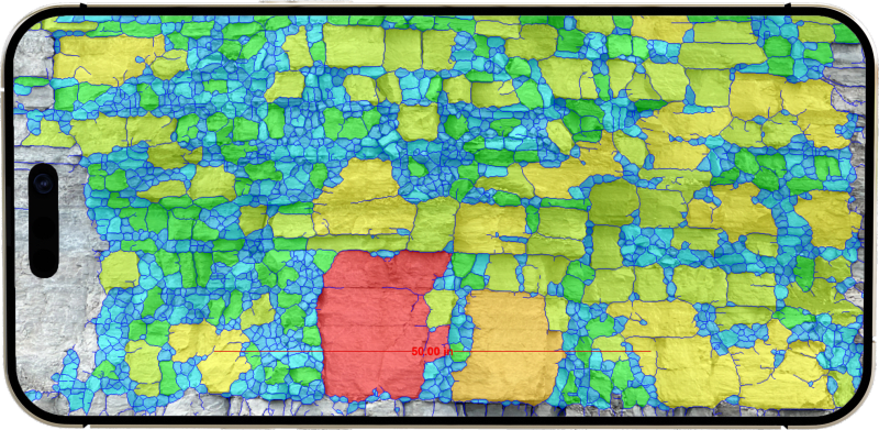
In open-cast mining, slope stability is not just a design factor—it's a matter of life, safety, and operational continuity. Every bench, wall, and overall pit slope must be carefully engineered to ensure it can withstand geological and environmental stresses without failure. What is Slope Stability? Slope stability refers to the ability of mine walls (slopes) to remain intact without sliding, collapsing, or deforming. Engineers evaluate this by analyzing rock and soil strength, geological structures, groundwater conditions, and external forces like blasting or heavy equipment vibrations. Key Factors Affecting Slope Stability: - Rock/soil properties (cohesion, friction angle) - Geological discontinuities (faults, joints, bedding planes) - Groundwater pressure and drainage conditions - Slope angle and bench geometry - External loads and dynamic activities (blasting, machinery) Why It Matters in Real Mining Operations: A slope failure can lead to: - Loss of life - Equipment damage - Production delays - Financial losses On the other hand, a well-designed slope ensures: - Safe working conditions - Efficient resource extraction - Long-term operational sustainability Engineering Approach: Modern mining uses advanced tools like geotechnical analysis, slope monitoring systems, and simulation models to predict and prevent failures. Engineers design optimal slope angles—balancing maximum ore recovery with minimum risk. For Engineering Students & Professionals: Understanding slope stability is essential for anyone in mining and geotechnical fields. It combines theory with real-world impact, making it one of the most practical and responsible areas of engineering. Mastering this concept means contributing directly to safer and smarter mining practices. Final Thought: In mining, success is not just measured by how much we extract—but by how safely and sustainably we do it. Slope stability stands as a reminder that engineering is ultimately about protecting both people and progress.